In my opinion, these little modules are terrific! With some modification, I use them in all of my robot projects. They are widely available from several manufacturers for between $1.50 and $5US. That said, this page is not affiliated with any particular manufacturer, does not endorse or guarantee the suitability of any product for any purpose, and does not offer any product for sale. All comments, corrections and complaints should be directed to bud@budryerson.com.
7 Sep 2023
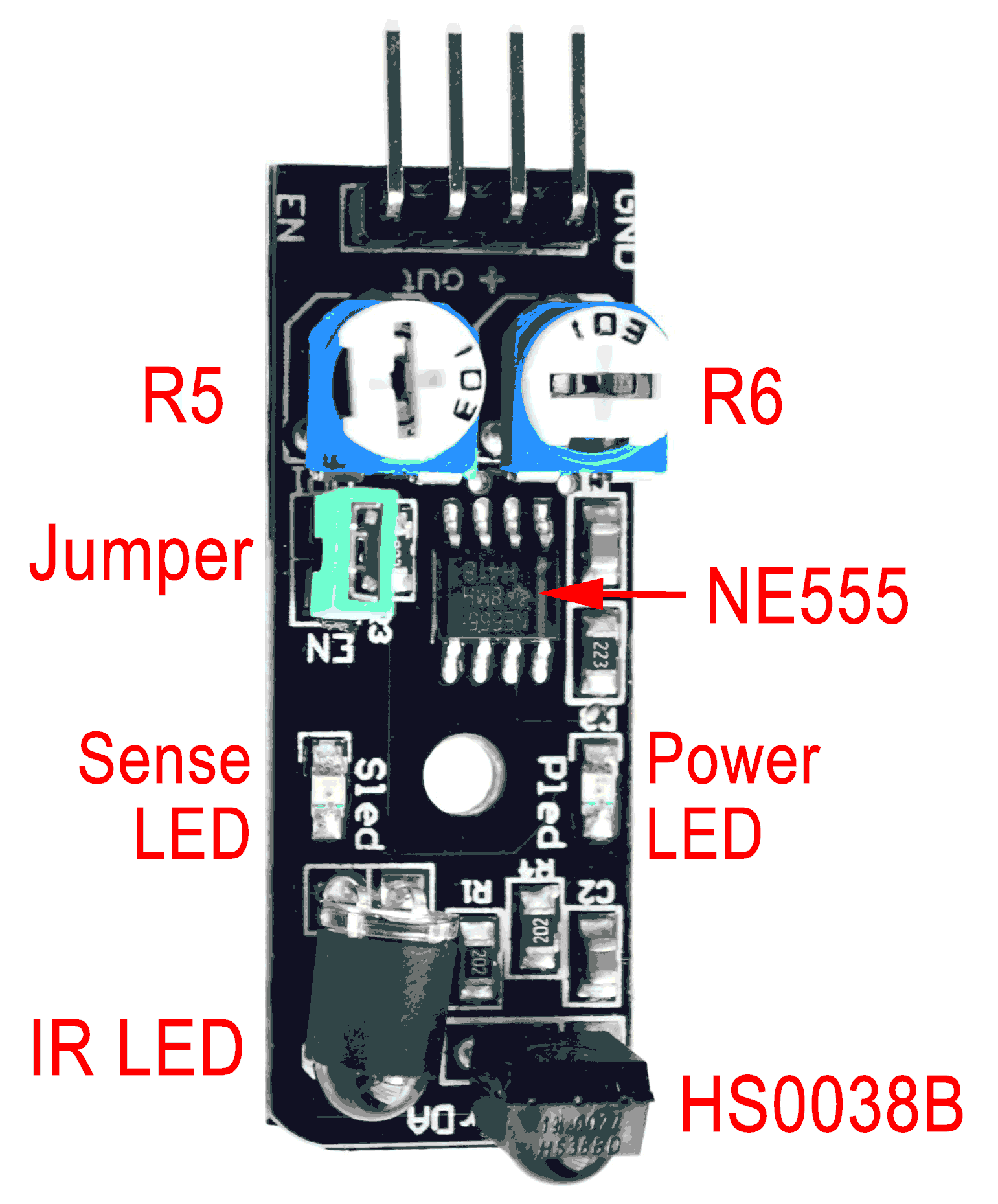
This sensor is known variously as the Keyes, KeyesIR or Keyestudio KY-032. It is the the functional equivalent of the IrBeady IR-08H, also known as the AD-032. The sensor uses a four pin connector. The functions of the pins are: Enable, Signal Output, Power and Ground. Different manufactures may label and order the pins differently. On the KY032 (pictured) the pins are labeled ( EN / out / + / GND ). On the IR-08H the pins are labeled ( - / + / S / EN). There are also two small potentiometers (variable resistors) on the board and one jumper (see picture).
Manufacturer's Specifications:
At the heart of the sensor is an NE555 chip configured to generate a 38kHz square wave. (The IR-08H version of this device uses an SN74LS00 chip for the same purpose.) The 38kHz signal is used to illuminate an IR (Infra Red) LED. Flickering IR light reflected by a nearby object is detected by a Vishay HS0038B IR receiver module (see data sheet). The receiver module incorporates an external, optical, 950nm IR filter and an internal, electronic, 38kHz band-pass filter that together make the module receptive only to IR light pulsing at that frequency.
There are two small variable resistors on the board: R5 (closer to the GREEN JUMPER) and R6. R6 is used to tune the 555 oscillator to exactly 38kHz. R5 will limit current to and dim the IR LED as it is turned counter-clockwise. Both adjustments together effect the sensitivity and range of the device. Without an oscilloscope or frequency counter, it is best to leave R6 as it came from the manufacturer or in the middle of its range. Turning R5 fully clockwise will overload the 555 and shut down operation. Leaving R5 in the fully clockwise position could overheat and eventually damage the device.
The HS0038B IR receiver module incorporates an AGC (Automatic Gain Control) that will quickly suppress a continuous signal of any frequency, including 38kHz (see excerpt from data sheet, below). Therefore, it is absolutely necessary to use the EN (Enable) pin to regularly turn OFF the 38kHz signal and allow the AGC circuit to relax. When the EN function is used correctly, the device will achieve its maximum sensitivity.
On most versions of this device, the IR LED is already covered with a small piece of black shrink-tubing; but I find that additional optical shielding is required. A small cardboard tube commonly used as packing material will work satisfactorily, as will a variety of other materials.
When the green JUMPER is installed (see picture), the EN line goes HIGH and a 38kHz signal is continuously applied to the IR LED. This jumper is used only for testing and to tune the oscillator to the correct frequency. The jumper must be removed for normal operation and proper use of the EN (Enable) function.
With the green JUMPER removed, pin 4 of the 555 timer is held LOW (RESET) by R3, a 22K pull-down resistor. When a HIGH condition is applied to the EN pin, the RESET condition is relieved and the 555 timer will begin to oscillate. Because the AGC in the IR receiver quickly saturates, the EN pin should not remain HIGH (Enabled) for more than 2 milliseconds at a time. The EN must go LOW for a short time before it goes HIGH again. This "strobing" of the receiver is done with programming.
From the HS0038BD data sheet:
These products are designed to suppress spurious output pulses due to noise or disturbance signals. Data and disturbance signals can be distinguished by the devices according to:
The data signal should be close to the band-pass center frequency of 38 kHz and fulfill the following conditions. After each burst of 10 to 70 cycles, a minimum gap time in the data stream of 10 cycles is needed. For bursts greater than 70 cycles, a minimum gap time in the data stream of greater than 4x the burst length is needed. When a data signal is applied to the IR receiver in the presence of a disturbance signal, the sensitivity of the receiver is reduced to insure that no spurious pulses are present at the output. Some examples of disturbance signals which are suppressed are:
Sample C++ code to Enable the 38kHz signal for 605µs (send 23 pulses to the IR LED) and test for a continuous LOW Output from the device to indicate the valid detection of an object:
digitalWrite( enablePin, HIGH);
// Enable the internal 38kHz signal.
microDelay( 210);
// Wait 210µs (8 pulses of 38kHz).
if( digitalRead( outputPin))
// If detector Output is HIGH,
{
objectDetect = false;
// then no object was detected;
}
else
// but if the Output is LOW,
{
microDelay( 395);
// wait for another 15 pulses.
if( digitalRead( outputPin))
// If the Output is now HIGH,
{
// then first Read was noise
objectDetect = false;
// and no object was detected;
}
else
// but if the Output is still LOW,
{
objectDetect = true;
// then an object was truly detected.
}
}
digitalWrite( enablePin, LOW);
// Disable the internal 38kHz signal.
Now wait at least 263µs before repeating.
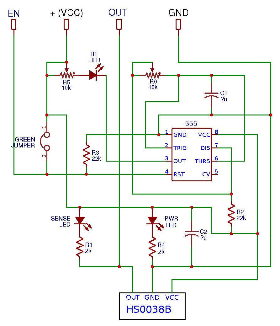
This schematic (below) of the KY-032 was created by examining the circuit board. It was my second attempt. I cannot guarantee its accuracy. It was drawn using the EasyEDA online electronic circuit design tool. The values of the two capacitors are not measured but thought to be: C1 = 0.24nf and C2 = 1.0µf.
An earlier version of this page stated that R5 was used to adjust the duty cycle of the 38kHz signal. That was wishful thinking and unfortunately not true. I want to thank Nick Sklenicka for gently pointing this out.
I also want to thank Arik Yavilevich and Ian Mander for their valuable contributions. Further comments and corrections will be appreciated.
Other sites of interest:
W3C Validated 21MAY2021